API globe valves are classified based on their body flow path configurations into straight-through, angle, and Y-pattern types. These designs differ in terms of fluid resistance, installation space requirements, and suitability for specific media. Selecting the appropriate structure during the process piping design phase—based on pipeline routing and fluid characteristics—can optimize piping layout, reduce operational energy consumption, and enhance valve stability.
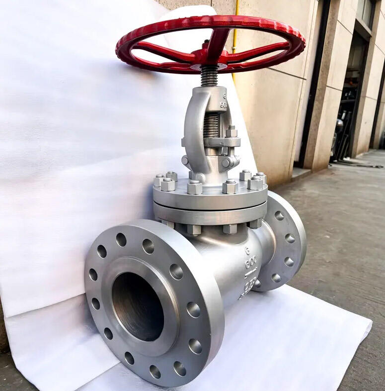
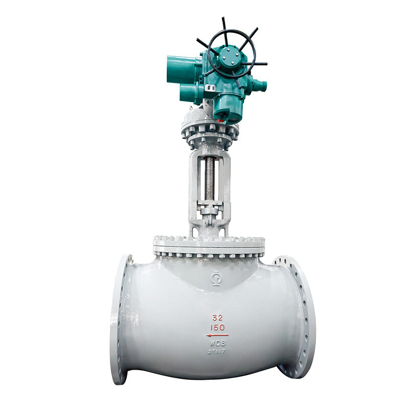
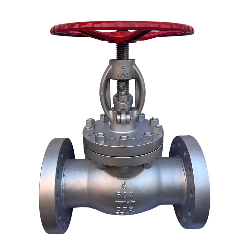
Straight-through API globe valves are the most widely used type in the industry; the inlet and outlet lie on the same axis, with the medium turning upward upon entering the valve body, passing through the seat, and then turning again to exit. This design features mature manufacturing processes and high spare-part interchangeability, making it suitable for the vast majority of conventional process pipelines. However, the flow path involves two turns, resulting in the highest fluid resistance among the three types and significant pressure loss in high-flow pipelines. Straight-through valves are the preferred choice for straight pipe sections with limited space; they are typically installed horizontally with the stem facing upward.
Angle API globe valves feature an inlet and outlet set at a 90-degree angle; the medium turns only once as it flows through, resulting in lower fluid resistance compared to the straight-through type. These valves serve the dual function of a valve and a pipe elbow, allowing for installation at pipeline turns; this eliminates the need for separate elbow fittings, simplifies the piping layout, and reduces the number of welded joints. They are frequently used at the inlets and outlets of heat exchange equipment and at pipeline corners. Since the valve body bears the thrust of the medium, proper pipeline support is essential during installation to prevent additional loads from being exerted on the valve body.
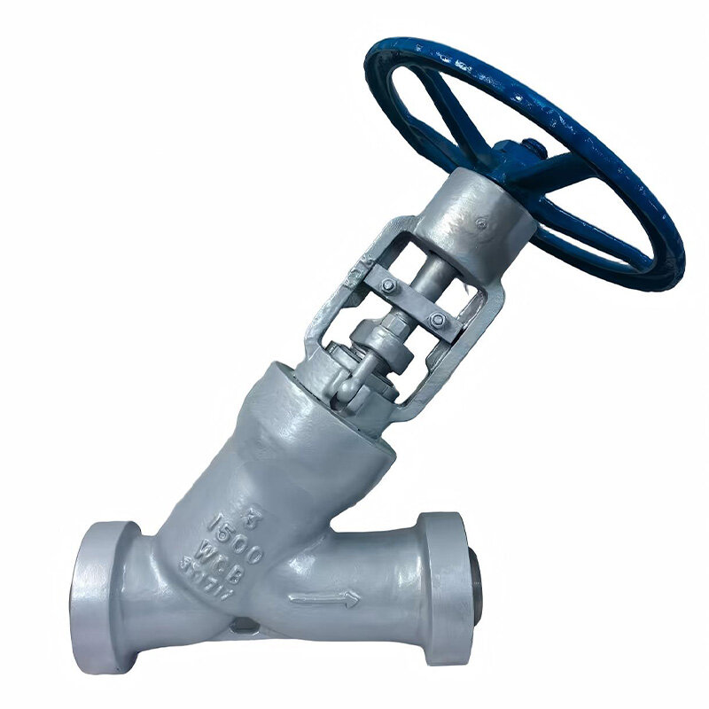
In Y-pattern API globe valves, the stem is inclined at an angle relative to the pipeline axis, creating a smoother flow path with minimal directional change and the lowest fluid resistance of the three types. The unobstructed flow path reduces erosion from the medium, making this design suitable for fluids containing small amounts of solid particles as well as for viscous media. However, Y-pattern valves have larger external dimensions and require more installation space; they are also more costly than straight-through API globe valves, making them unsuitable for sections where space is constrained. All three types of API globe valves share the same sealing principle—achieving a seal by pressing the disc against the seat—and utilize hard-faced (stellite-welded) sealing surfaces. However, differences in flow path design result in varying locations of medium impingement. In straight-through valves, stronger fluid turbulence occurs in the seat area, leading to accelerated wear on sealing surfaces due to prolonged throttling erosion; conversely, Y-type valves feature a smoother flow path with less erosion damage, making them suitable for long-term throttling applications.
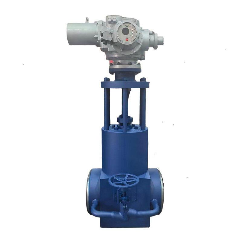
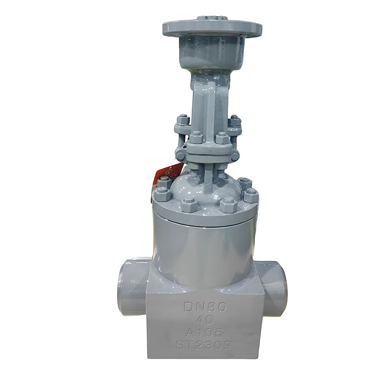
API globe valve bodies are available in cast steel and forged steel. Cast steel bodies allow for larger bore sizes, making them suitable for main process pipelines, whereas forged steel bodies offer a dense internal structure free from casting porosity, making them ideal for small-bore, high-temperature, and high-pressure instrumentation lines. Forged steel API globe valves feature a compact design and excellent high-pressure resistance, finding widespread use in high-temperature, high-pressure steam piping.
When selecting an API globe valve, one must verify pressure-temperature ratings in addition to the flow path configuration. Since allowable working pressure decreases as temperature rises for various valve body materials, selection should not rely solely on nominal pressure ratings; instead, one must consult standard pressure-temperature curves to ensure the operating point falls within the rated limits. Alloy steel internals are selected for high-temperature applications, while materials meeting low-temperature impact toughness requirements are chosen for cryogenic service to mitigate the risk of low-temperature embrittlement.
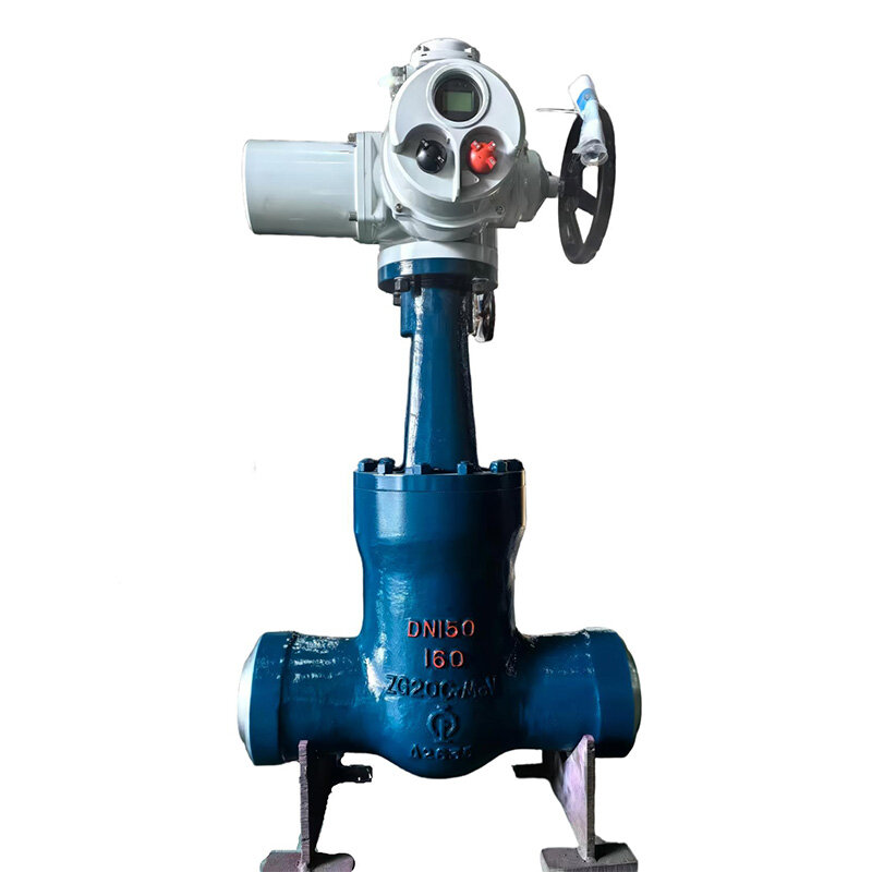
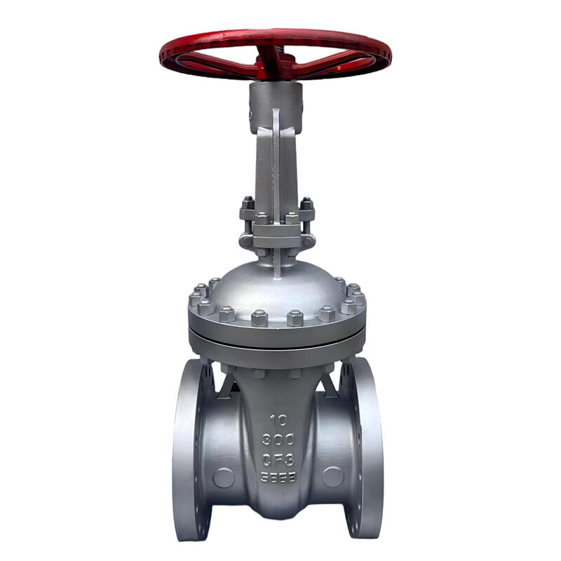
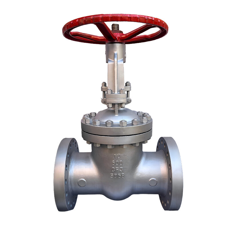
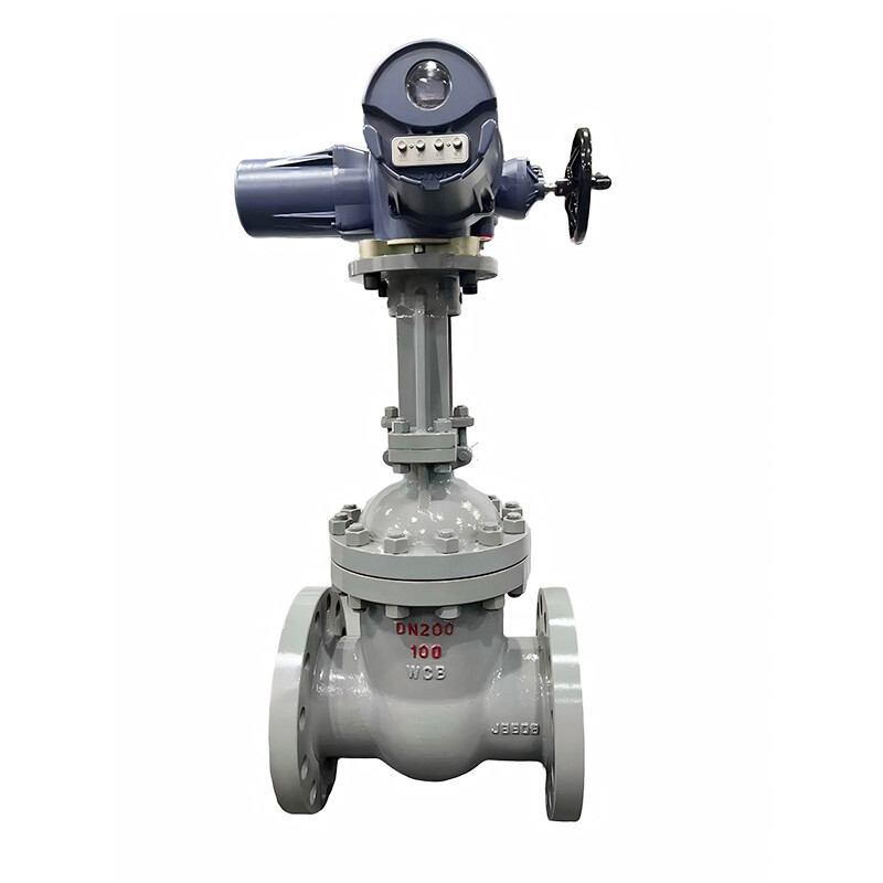
Compared to API 600 gate valves, gate valves have larger body dimensions, longer travel distances for opening and closing, and lower flow resistance; API globe valves are compact, have short travel distances, and offer throttling capabilities. API 600 gate valves are preferred for pipelines requiring high flow capacity without the need for flow regulation, whereas API globe valves are chosen for scenarios requiring frequent flow adjustment or branch line isolation. These valve types are not interchangeable; selection should be based on specific process and functional requirements.
During installation, angle-pattern API globe valves require a specific flow direction, meaning inlet and outlet ports cannot be reversed; for Y-type API globe valves, the inclined stem requires sufficient clearance to prevent interference between the operating mechanism and pipe supports. When installing any type of API globe valve, the valve body must not bear the weight of the piping; independent supports or hangers should be used to carry the load and prevent valve body deformation that could compromise the seal.
Regarding operation and maintenance, the internal cavity of a Y-pattern API globe valve is easier to clean, facilitating the removal of deposits during disassembly and servicing. In contrast, straight-through valves have more "dead zones" where viscous media tend to accumulate, necessitating regular cleaning. Regardless of the specific API globe valve type, periodic inspection of seat sealing performance and timely addressing of sealing surface wear are essential for throttling applications.
API globe valves offer various flow path configurations to suit different piping layouts and media conditions. Understanding the characteristics of straight-through, angle, and Y-pattern API globe valves—and selecting the right model based on available space, the medium, and flow regulation requirements—allows for optimized piping design and ensures the stable, reliable operation of the fluid control system.